Thermal solution
Thermal Instructions
Due to the relatively high performance of the M1 and L1 development boards, the bottom core module generates significant heat during extended high‑load operation. Installing a heatsink can enhance heat dissipation and help ensure stable device operation.
Summary of material purchase links
Item |
Specification |
链接 |
|---|---|---|
Screw |
M2.5*14, black 304 stainless steel hex socket head cap screw |
|
Brass standoff |
M2.5*3 double-ended hexagonal brass standoff |
|
Cool fan |
With adhesive backing, for single or dual fans |
|
Thermal pad |
Thermal pad |
|
Cool fan |
4B PWM speed-adjustable cooling fan |
Thermal solution mounting scheme
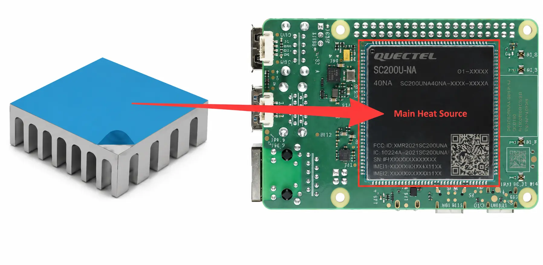
Attach the heatsink with adhesive backing to the primary heat source.
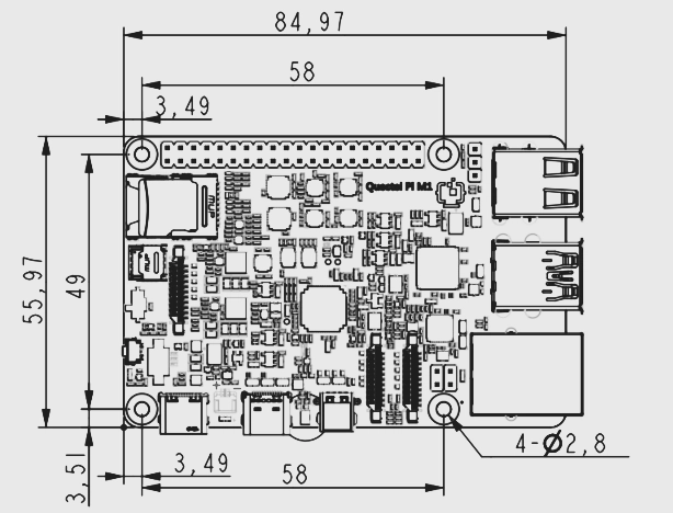
Use the mechanical mounting holes around the development board to secure the heatsink. For the exact mounting hole positions, refer to the dimension drawing below.
Note:For better heat dissipation, it is recommended to fill the gap between the heatsink and the heat source with a thermal pad or thermal grease.
Passive Cooling Example
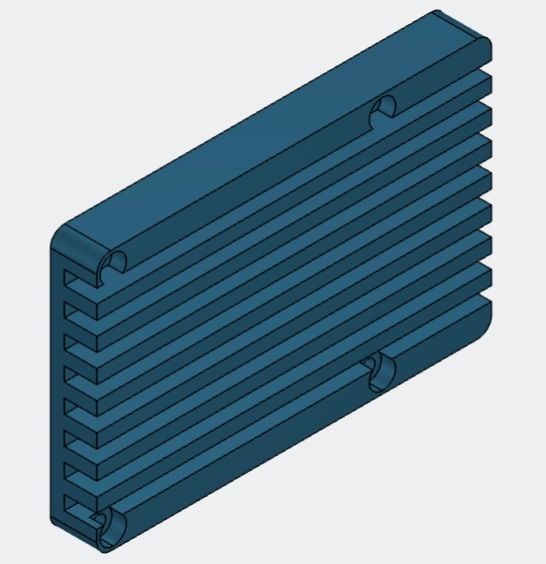
The following section introduces a simple passive heatsink for developers’ design reference. This heatsink is mounted using the mechanical mounting holes on the development board.
Note:This component is a custom part from Quectel and is not a standard off‑the‑shelf item.
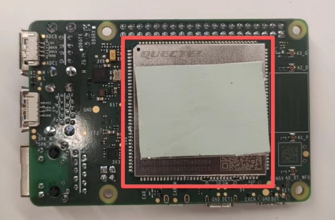
Attach the thermal pad to the rear module.
Align the heatsink with the mounting holes on the development board.
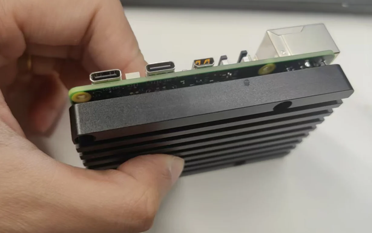
Use 4 M2.5×14 nuts and 4 M2.5×3 brass standoffs to secure the assembly and complete the installation.
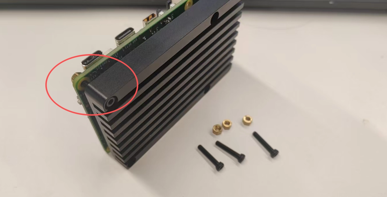
The completed installation is illustrated below.
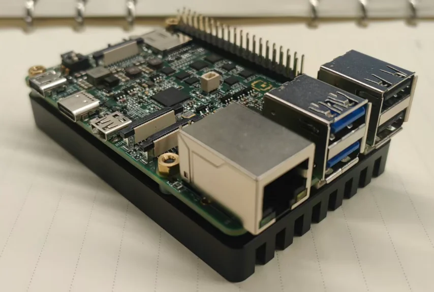
Note: This heatsink is intended solely as a design reference demo. Whether it meets the heat dissipation and cost requirements of the actual application must be evaluated by developers based on their specific application scenarios and requirements.
Heatsink reference model:
Active Cooling Example
Fan without temperature control
Active cooling requires powering the fan. The 5V pin on the 40‑pin header can be used to supply power to a 5V fan.
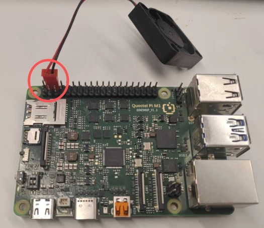
Secure the fan to the rear heatsink. Refer to the following:
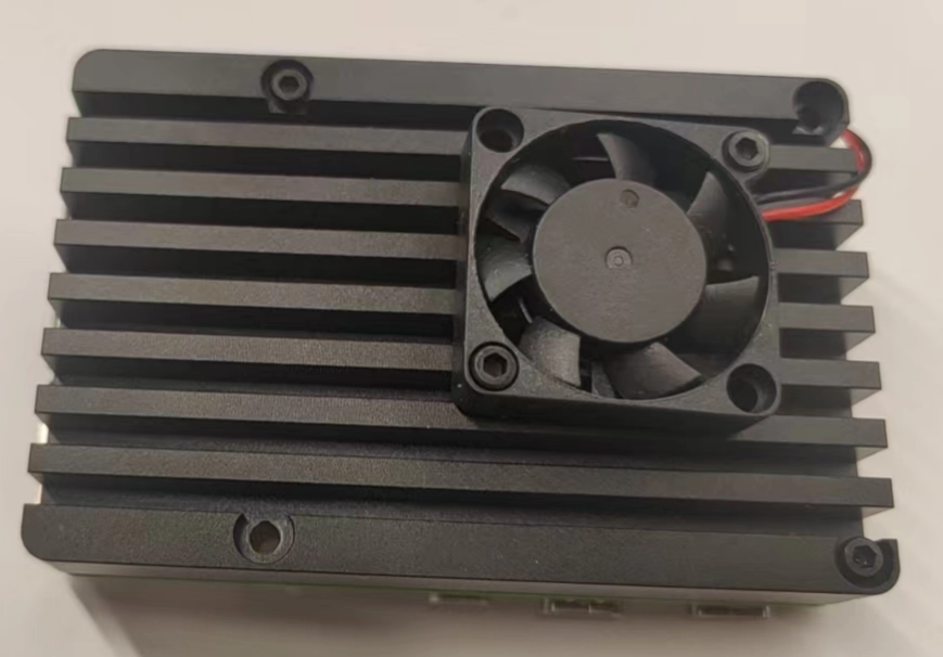
Note:This solution does not allow fan speed control. The fan will spin as soon as the development board is powered on.
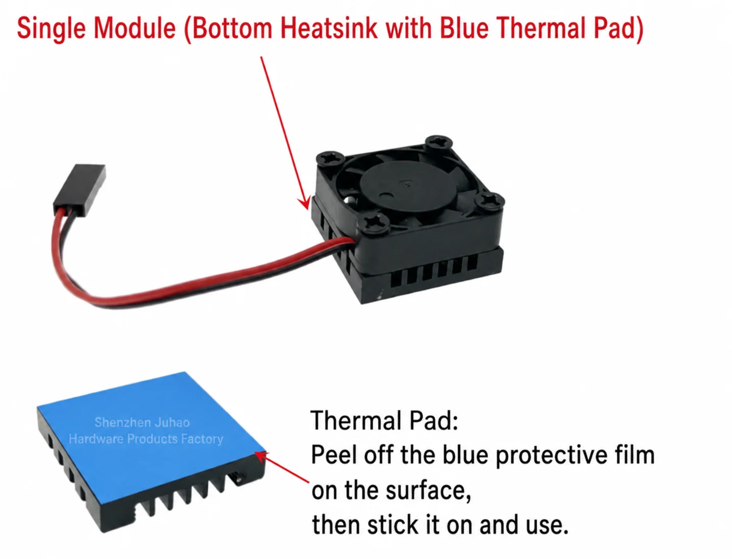
Developers may also choose products of this type that integrate a heatsink with an adhesive backing.
Temperature‑controlled fan test
On the 40‑pin header of the development board, PIN33 provides PWM functionality, which can be used for fan speed control.
2‑Pin Fixed‑Speed Fan Control
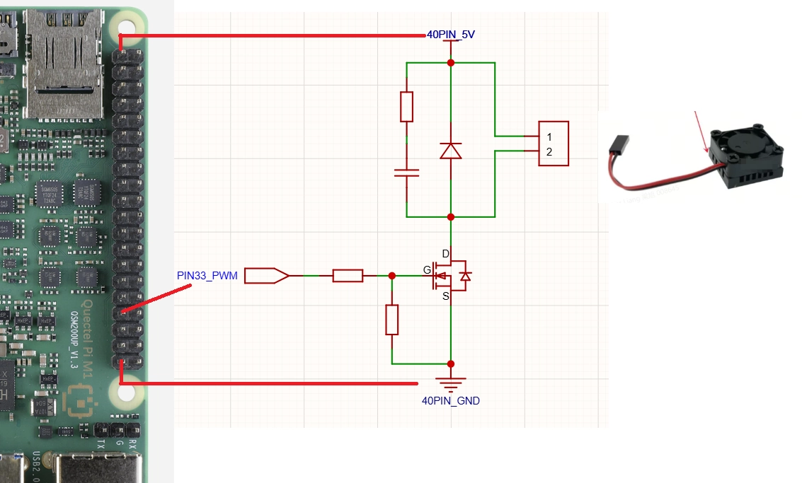
For a 2‑wire fan without a speed control interface, the following reference circuit can be used in conjunction with the PWM pin to achieve fan speed control.
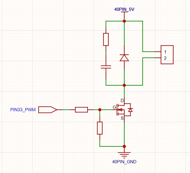
Electrical connection diagram
3‑Pin Variable Speed Fan Control
Background process monitors/sys/class/thermal/thermal_zone*
and cyclically reads the temperatures of the multiple CPU cores, takes the highest value, and configures the fan PWM duty cycle based on that highest temperature.
|
|
|---|---|
<30℃ |
0 |
30~40℃ |
64 |
40~50℃ |
128 |
50~60℃ |
192 |
>60℃ |
255 |
Hardware Installation and Wiring Diagram
This test uses a Cool fan. Connect it to the corresponding pins on the M1/L1 40‑pin header as shown in the diagram below.
Fan Pin |
M1/L1 Development Board Pin (40‑PIN) |
|---|---|
Red wire (Power positive) |
PIN2 |
Black wire (Power negative) |
PIN6 |
Blue wire (PWM) |
PIN33 |
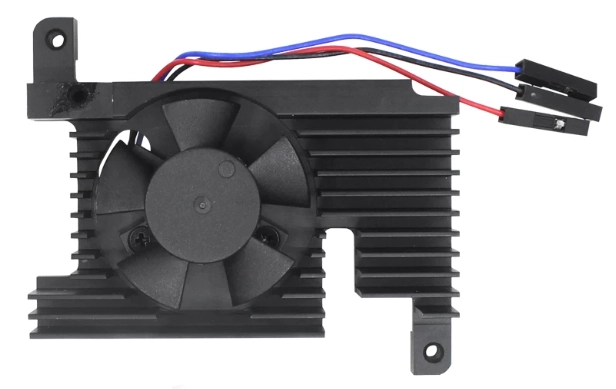
Actual installation is as follows:
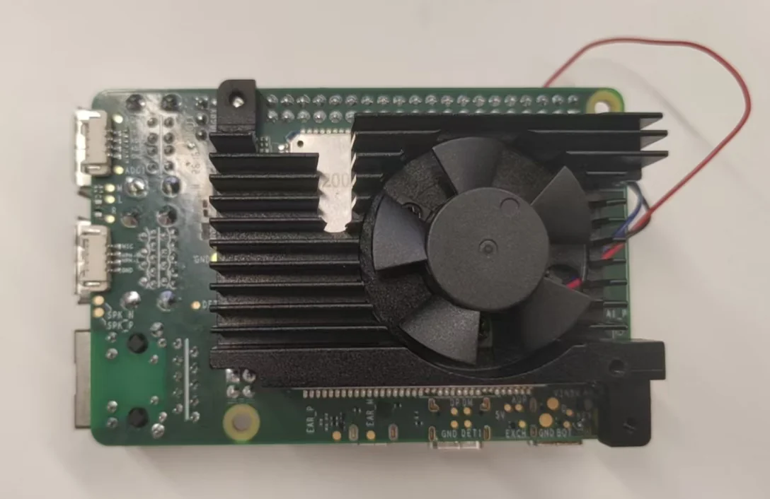
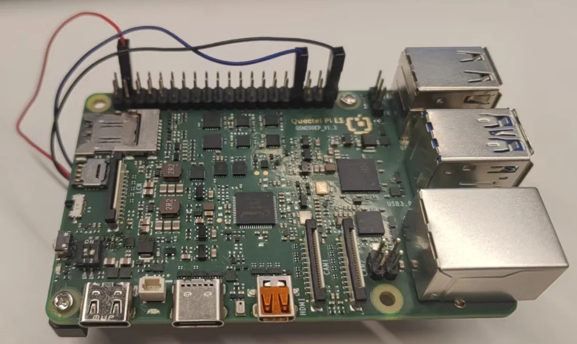
Note: Heatsinks from different manufacturers may have varying compatibility with this product. Developers should evaluate accordingly.
Software Testing Procedure
By default, the fan function is disabled. After power‑on, enter the following commands in adb to check the status of the fan service.
adb shell
40pin-ctrl fan status # View the current status of the fan service (bound if not enabled, enable if active)
40pin-ctrl fan enable # Enable the fan service; after enabling, you can check whether the status shows "enable"
40pin-ctrl fan disable # Disable the fan service (only needed to stop the test)
Enter the following in the first terminal.
40pin-ctrl fan enable
40pin-ctrl fan status
#M1
watch -n 1 'PWM=/sys/bus/platform/devices/1c40000.qcom,spmi:qcom,pm6125@1:qcom,pwms@b300/pwm/pwmchip0/pwm0; p=$(cat "$PWM/period"); d=$(cat "$PWM/duty_cycle"); echo $(( (d * 255 + p / 2) / p ))'
#L1
watch -n 1 'PWM=/sys/bus/platform/devices/1c40000.qcom,spmi:qcom,pm2250@1:qcom,pwms@be00/pwm/pwmchip2/pwm0; p=$(cat "$PWM/period"); d=$(cat "$PWM/duty_cycle"); echo $(( (d * 255 + p / 2) / p ))'
Check whether the current temperature and PWM duty cycle match.
Open a second terminal and perform the heating (temperature‑raising) operation.
for i in 1 2 3 4; do
  yes > /dev/null &
done
If the temperature rise in step 3 is insufficient, you can increase the load.
for i in $(seq 1 $(nproc)); do
  yes > /dev/null &
done
Check whether the temperatures and fan PWM duty cycles in the two terminals match the values in the table.
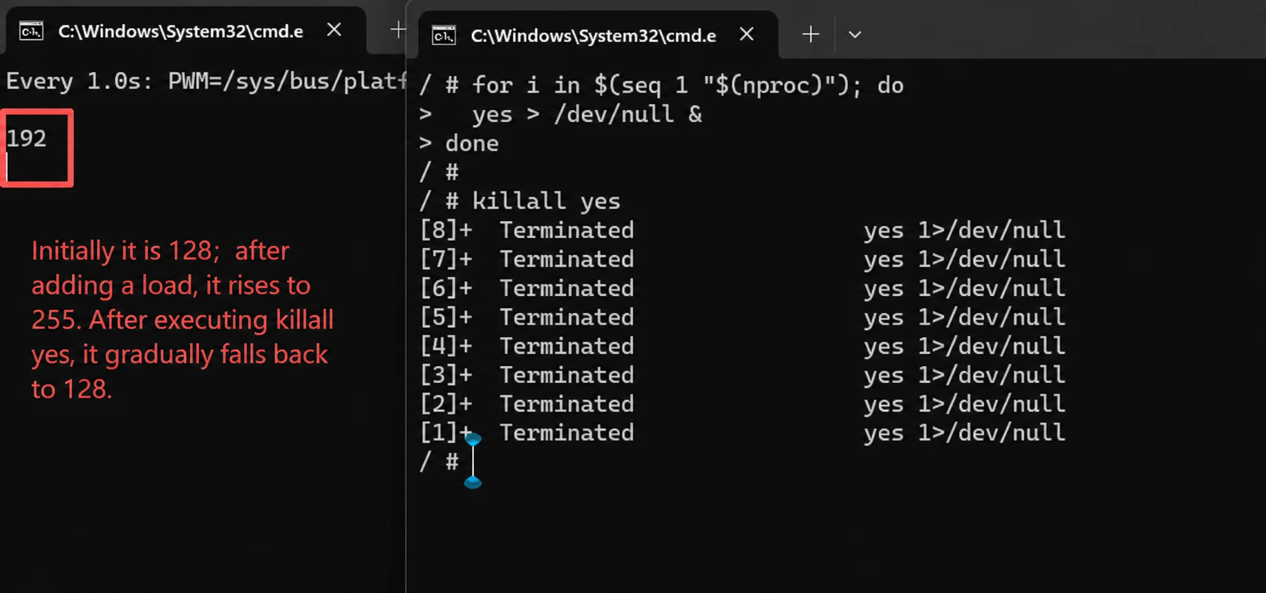
After the test ends, stop the load.
killall yes